Introduction
MELEC’s DC-Pulse Power Controller is developed to provide the most flexible and stable DC Pulse Controller for Plasma Surface Engineering on the market.
Flexible programming and synchronization and a wide range of software features gives researchers and engineers a tool that is unique worldwide. Every model of MELEC’s DC-Pulse Power Controller can be used for HiPIMS, MF or Bias applications.
System overview
The following schematic diagram (Figure 1) shows the patent-registered MELEC power electronic circuit. With this circuit it is possible to drive the output E1 and E2 in DC, Unipolar- and Bipolar Mode by switching Transistor T1, T2, T3 and T4. G1 and G2 are two floating DC-Power Sources which charge the Capacitors C1 and C2. MELEC‘s DC-Pulse Power Controller has no integrated DC-Source. The reason is the possibility to provide symmetric- and asymmetric bipolar voltage level on the outputs E1 and E2 by closing or opening S1 and S2. For symmetric bipolar output pulses one DC Source is needed and S1 and S2 has to be closed.
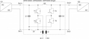
Figure 1: MELEC Power Electronic Circuit
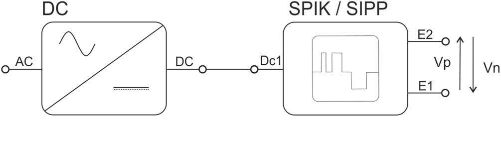
For a better understanding of applications (later on in this text) a transformation to a simpler system symbol is useful. The Figure 2 shows the transformed power electric circuit into this system symbol. Connector Dc1 and Dc2 on the symbol represent the plus and minus connector of each input (Dc1 = Dc1+ & Dc1-). The circuit in Figure 2 shows the case for asymmetric output at E1 and E2.

Figure 2: Power Electronic Circuit for asymmetric output
If the switch S1 and S2 of figure 2 are closed the capacitor C1 and C2 are connected to the same DC source. This means that the Dc2 is not present anymore and the power electronic circuit transforms to a system symbol with one DC connector (Figure 3) only. This case represents the symmetric output at E1 and E2.

Figure 3: Power Electronic Circuit for symmetric output
Symmetric Bipolar Pulse Output
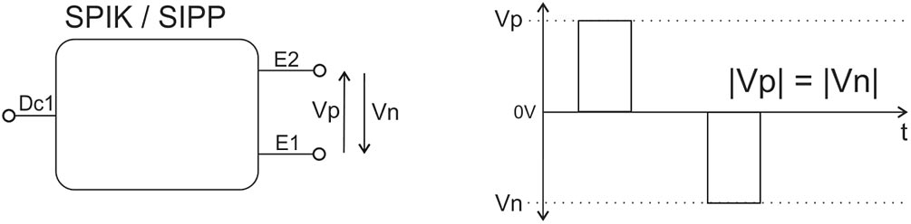
Figure 4: Symmetric Output Voltage
Asymmetric Bipolar Pulse Output
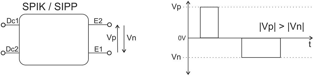
Figure 5: Asymmetric Output Voltage
Note: The higher voltage level can change from positive to negative. Therefor it is possible to drive the output in modes like |Vp| > |Vn| or |Vp| < |Vn| or |Vp| = |Vn|.
Output Signal Control
Every MELEC DC Pulse Power Controller has different integrated possibilities to generate output functions. As an example the SPIK1000A generator has the possibility to generate Unipolar +/-, Bipolar or bypass the DC Power directly from the connected DC source. The SIPP2000 generator on the other hand can be programmed by the MELEC FPPG (Free Pulse Pattern Generator) and also integrate the functions of the SPIK1000A.

Figure 6: DC-Pulse-Controller Mode
DC Bypass:
The DC Pulse Controller bypass the voltage, current and power from the DC Source directly to the outputs E1 and E2. It is possible to switch in DC+ or in DC-. Therefor the polarity on E1 and E2 is changing.

Figure 7: DC Bypass Mode
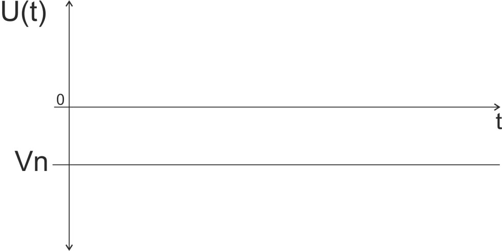
Figure 8: DC Voltage Output
Unipolar
The unipolar mode is the first periodic-switching-mode of the SPIK and SIPP series. It is possible to switch the output in unipolar positive (UP+) and unipolar negative (UP-).
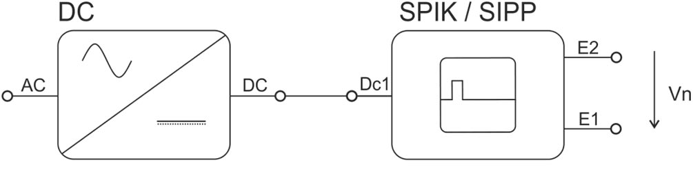
Figure 9: Unipolar Mode
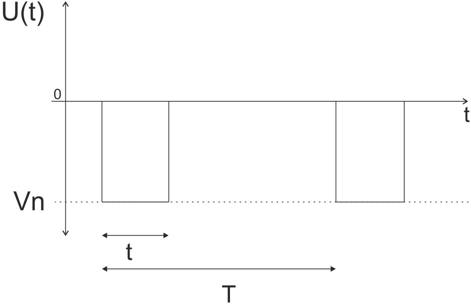
Figure 10: Unipolar Output Voltage
Bipolar
In the bipolar mode the voltage level is alternating between E1 and E2.

Figure 11: Bipolar Mode

Figure 12: Bipolar Voltage Output
FPPG
In the FPPG (free pulse pattern generator) mode the voltage level is alternating between E1 and E2 and can be programmed by the user. This means that every pulse can be choosen by polarty, pulse on time and pulse off time. The period time (T) is the addition of all pulses on time and there off times.

Figure 13: FPPG Mode

Figure 14: FPPG Voltage Output